Extruder velocity advance (EVA) has been implemented in all major 3D print fimwares (everyone has their own name for it). It is intended to increase extrude width accuracy and reduce extruder ooze after extrusion ends. Here's my overly simplified explaination of what it does, how it is useful and its challenges.
For this explaination, I'm going to use an example extruding move of 0.5 seconds that starts and ends at zero velocity, and then continues on without extruding.


For this explaination, I'm going to use an example extruding move of 0.5 seconds that starts and ends at zero velocity, and then continues on without extruding.

You can see above the velocity and position porfiles. Tthe velocity ramps to 60mm/s and back down before continuing on. The length of the extrude move is about 22.8mm. In an ideal situation, the extrusion volume would be proportional to the distance traveled. For each mm the head moves, we want a precise amount of plastic to to be deposited on the part.

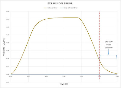
Using a simple fluid flow model, the above graph shows the ideal volumetric extrusion compared to the simulated "real" output. The gap between the two lines is the extrusion rate error. The larger the gap the worse the error. Ideally they would be coincident. The goal of EVA is to "over extrude" in such a way as to get the real output and the ideal output to match as closely as possible. A graph of the error looks like this:

If one squints at the graph above, it looks a little like the velocity profile from the first graph. This would suggest that the error in extrusion rate may be related to the velocity of the motion ( There are theories of fluid flow with big names that explain/model this behavior). It should also be noted that the tail of the error that extends beyond the end of the extrude move (0.5s) is what would likely ooze out during the following non-extruding move. Idealy this tail would not exist.
If we advance the filament by the volume of the error while moving, and remove the advance as we come to a stop, we should be able to counter this error.

Combining the ideal extrude volume (red dotted line) with this extrude compensation (yellow line) above gives us the blue line above. Note that although it attempts to overextrude, it still starts and ends at the same volume as is ideal. So in effect, the same amount of filament will be fed into the extruder, only with a different profile that we hope will give us the correct output as the move is made.

Above we can see the simulation of the compensated extrude rate (dark blue line). As we would hope, it ovelaps with the ideal extrude rate. If we look at the extrude volume error, we see a significant improvement:

The dark blue line at the bottom is the error after compensation. Notice the volume of the error is very near zero at the end of the extrude move. This should result in significanly less ooze (stringing and bulging corners), while also helping the width of an extrude to stay more consistent over it's entier length (less thining in the middle). Keep in mind that these results were generated with a simple fluid flow model, so in the real world it is unlikely that this compensation technique would perfectly eliminate ooze related problems. Having said that, even if it is not perfect, this offers improvement over no compensation.
The challenge with this compensation, is that it requires tuning a coefficient to reduce the error each time there is a major change in the printer extrude parameters. This is due to the fact that the compensation is tightly tied to the resistance of the extrusion by the follow parameters:
- Plastic type (ABS, PLA, PETG... )
- Hot end temperature
- Nozzle diameter
- Nozzle wear
- Hot end thermal stability
- Extruder compliance (Bowden vs. Direct)
If this parameter is set too high there will be over extruding early in the move (or even skipped extruder steps in extreme cases), and extrude starvation near the end. If the parameter is too low, then the advantages of this technique are not fully realized. Unfortunately, there is no current model for taking into account all of the above factors (and more) and giving an accurate compensation coefficient. This leaves it to the operator tune this by trial and error. Most firmwares will give an initial value that works reasonably well for most people. This is still better than nothing, but leaves room for improvement.
In a future post I will go through the tuning process and include pictures to help highlight the improvement and aid in the tuning by other people trying to maximize their print quality.
Mostly I do not comment on any post, but your blog has lots of knowledge. it's forcing me to do this. it has really amazing content please share more information with us.UHMW Conveyor Components
ReplyDeleteA normal technique for avoiding laws that prohibit, constrain, or aggressively tax playing is to find the exercise just outdoors the jurisdiction that enforces them, in 먹튀프렌즈 a extra "playing pleasant" legal surroundings. Gambling establishments usually exist close to state borders and on ships that cruise outdoors territorial waters. Gambling exercise has additionally exploded current years|in recent times|lately} in Native American territory.
ReplyDelete